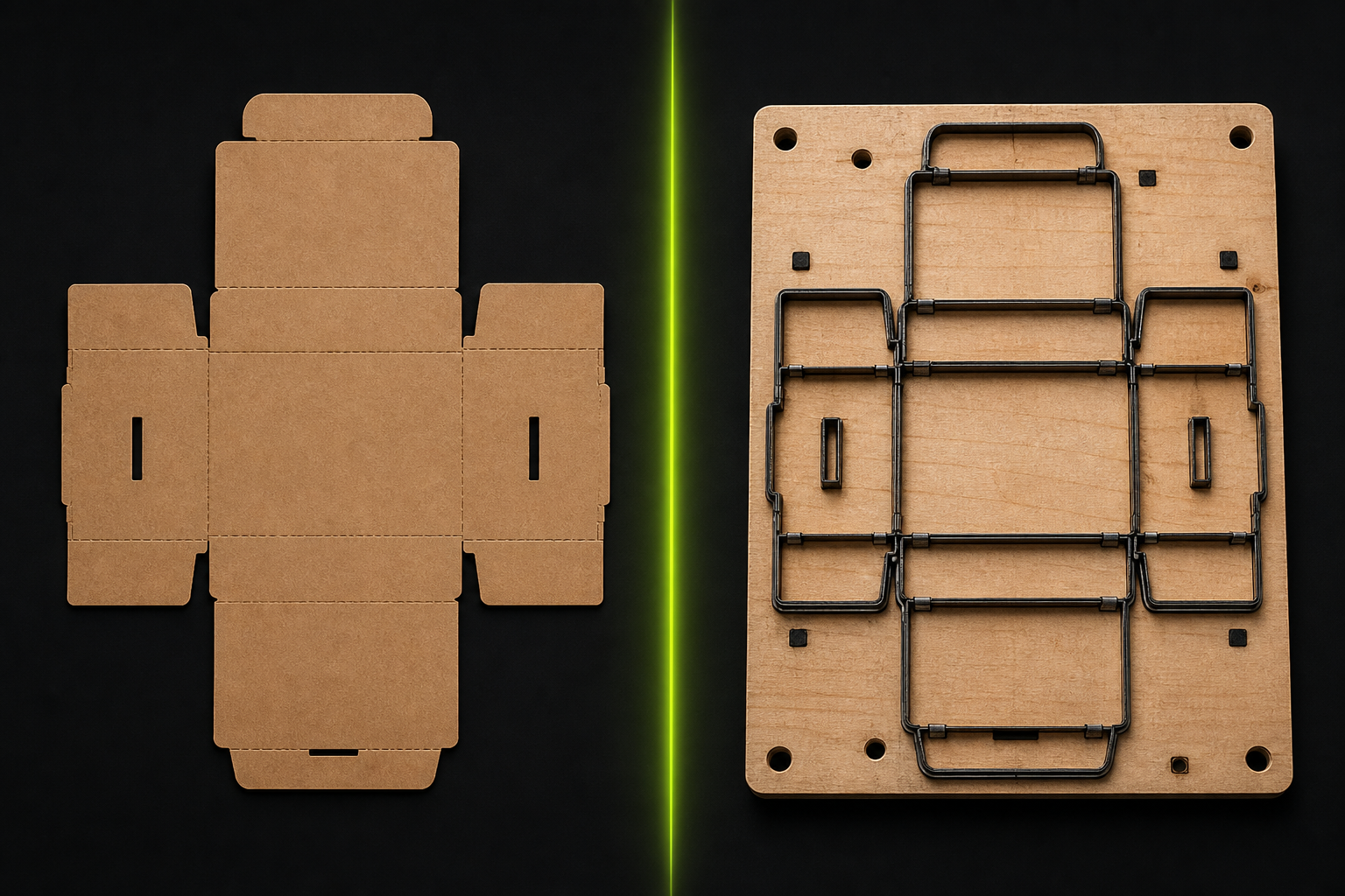
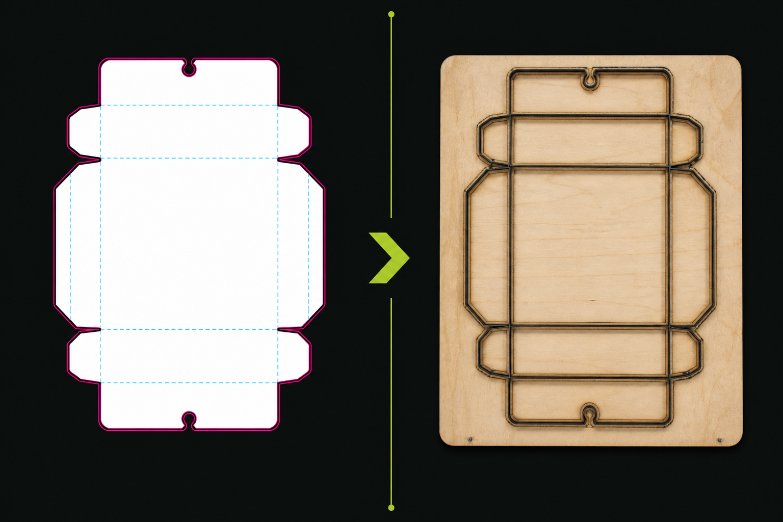
A die designer prepares vector cut, crease and perforation from the dieline so the die shop can laser the board or set RULE die and matrix. One millimetre wrong in crease channel or rule thickness becomes scrap and line stoppages across thousands of sheets.
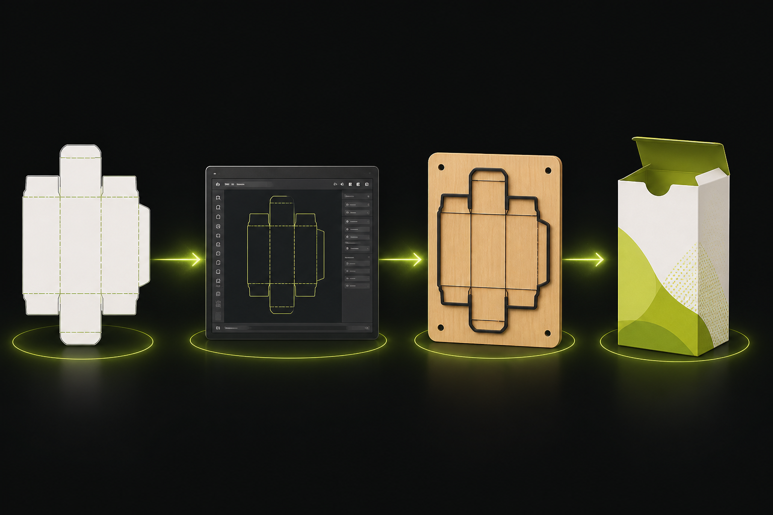
Typical workflow: graphic designer gets the dieline → places print art → die designer separates Cut/Crease for the machine → laser shop cuts the board → lithography builds print plates.
This page is a technical reference for common die-shop and die-cut standards — align knife and matrix specs with your printer before ordering a die.
Path: dieline → die designer → die → litho → print.
Technical principles of die design
Technical line colour coding (Spot Colors)
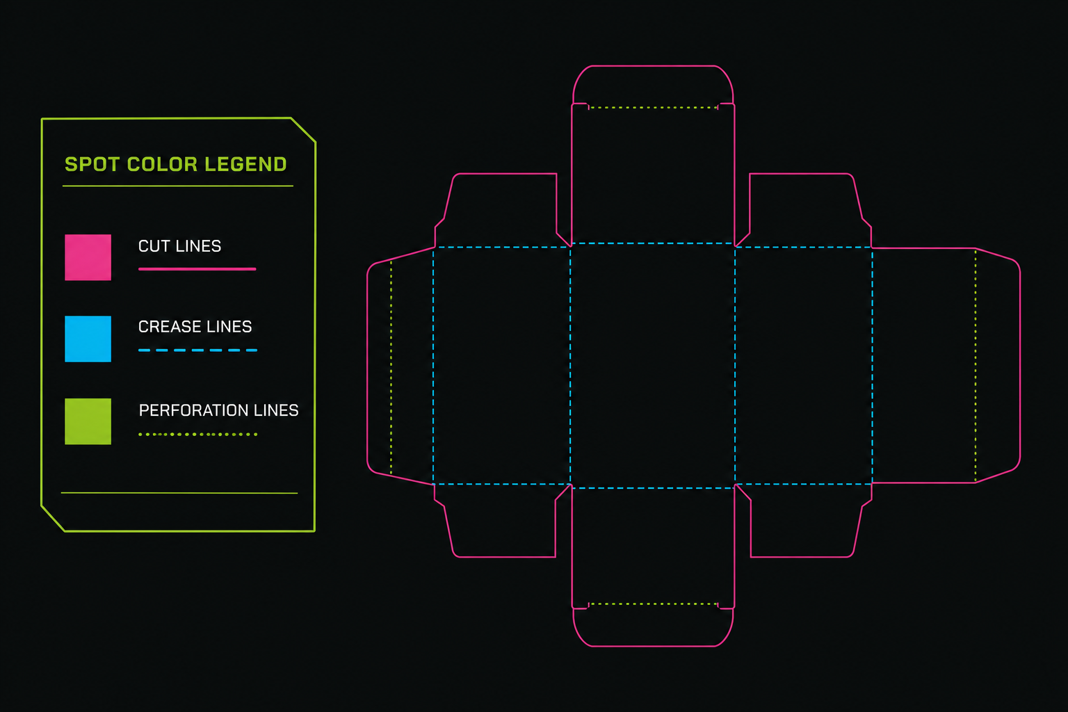
Magenta for cut, Cyan for crease, green for perforation — PDF layer names must match the lithography workflow.
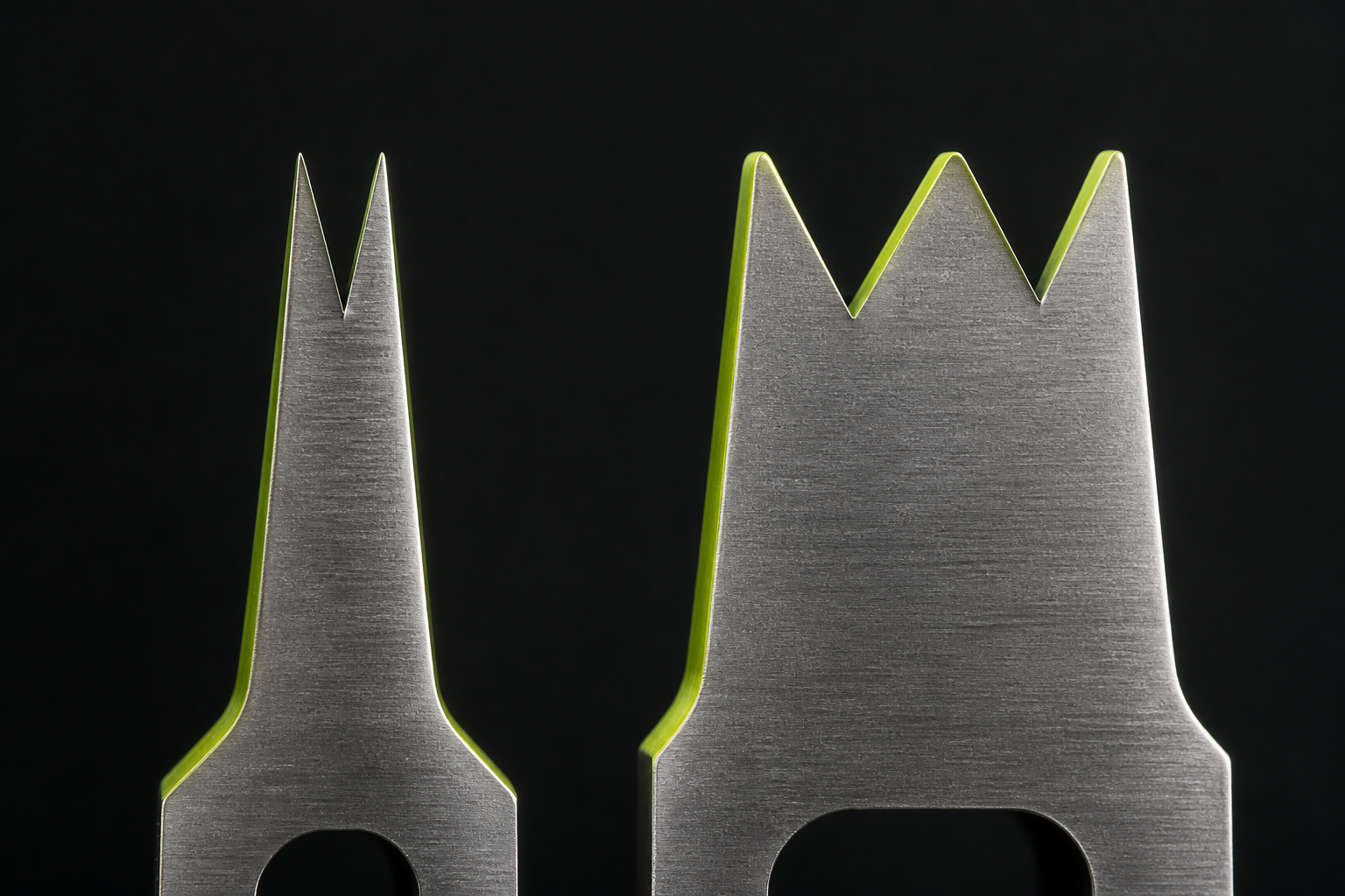
2pt and 3pt rule
Thinner rule for thin board and fine detail; 3pt for kraft and thick board. Bevel angle affects rule durability.
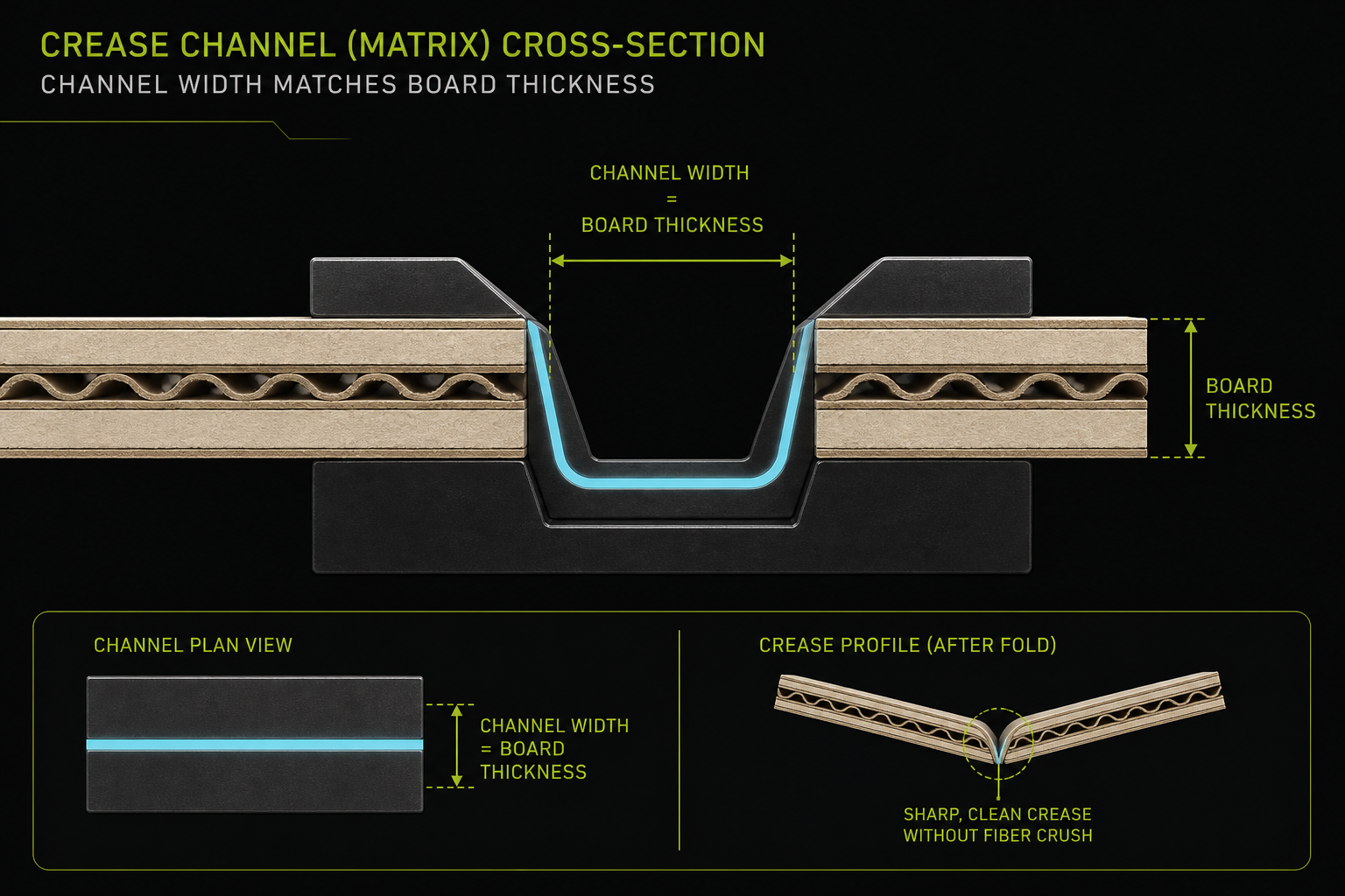
Matrix channel and crease
Channel width matched to board thickness — too narrow cracks; too wide folds loosely. Typically 0.4–1.2 mm by grammage.
Rule spacing and bridges
Minimum distance between parallel cuts and between cut and crease to stop board breakage and sheet tear on press.
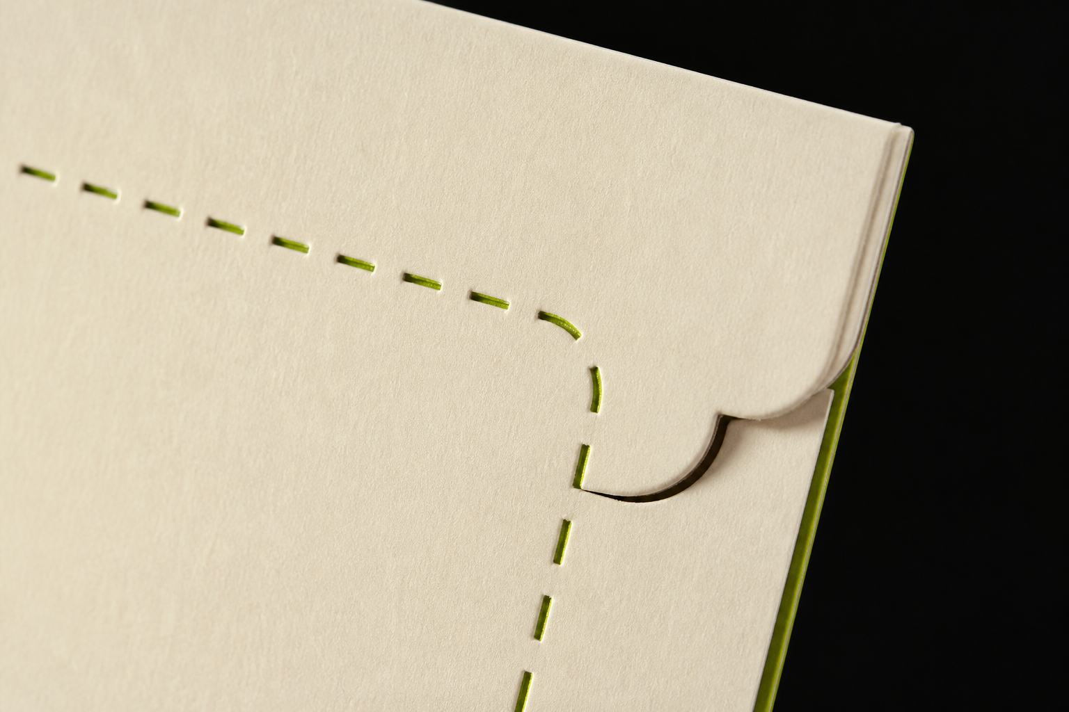
Perforation
Dash pattern with set gaps for tear-open; must not be confused with crease. In CNC export, separate from full cut.
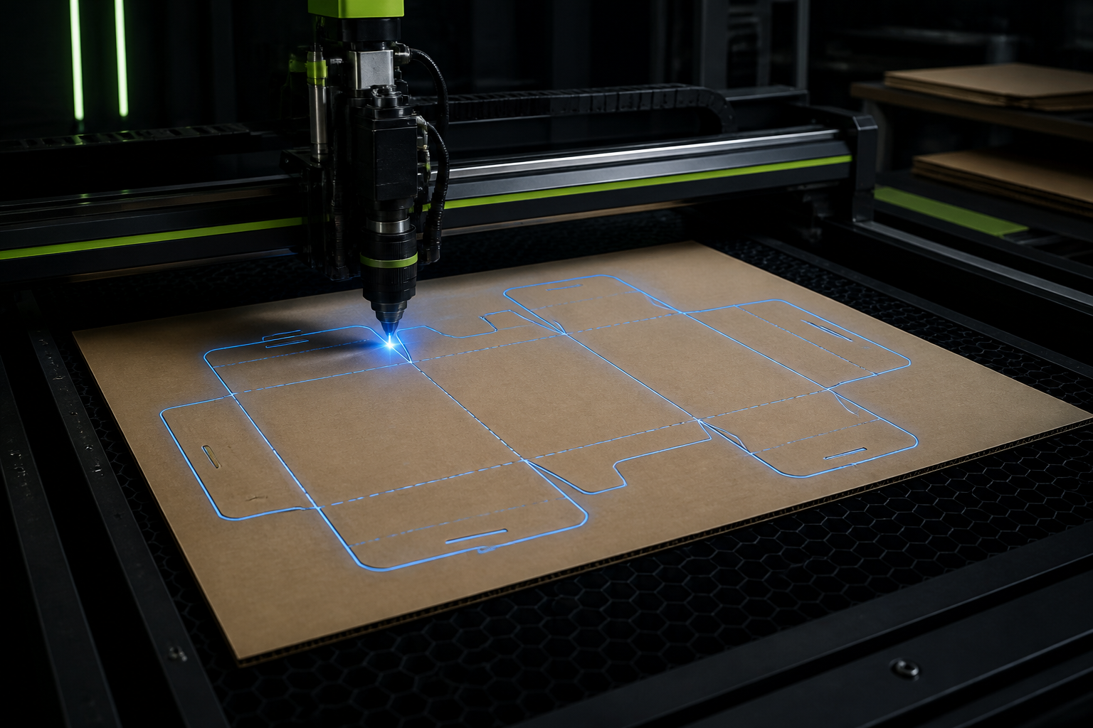
CNC and laser export
DXF/SVG in millimetres, closed paths for cut, no duplicate nodes — ready for AutoCAD, Kongsberg and laser cutters.
Platen die-cutting
Laser die, RULE die and platen die-cut
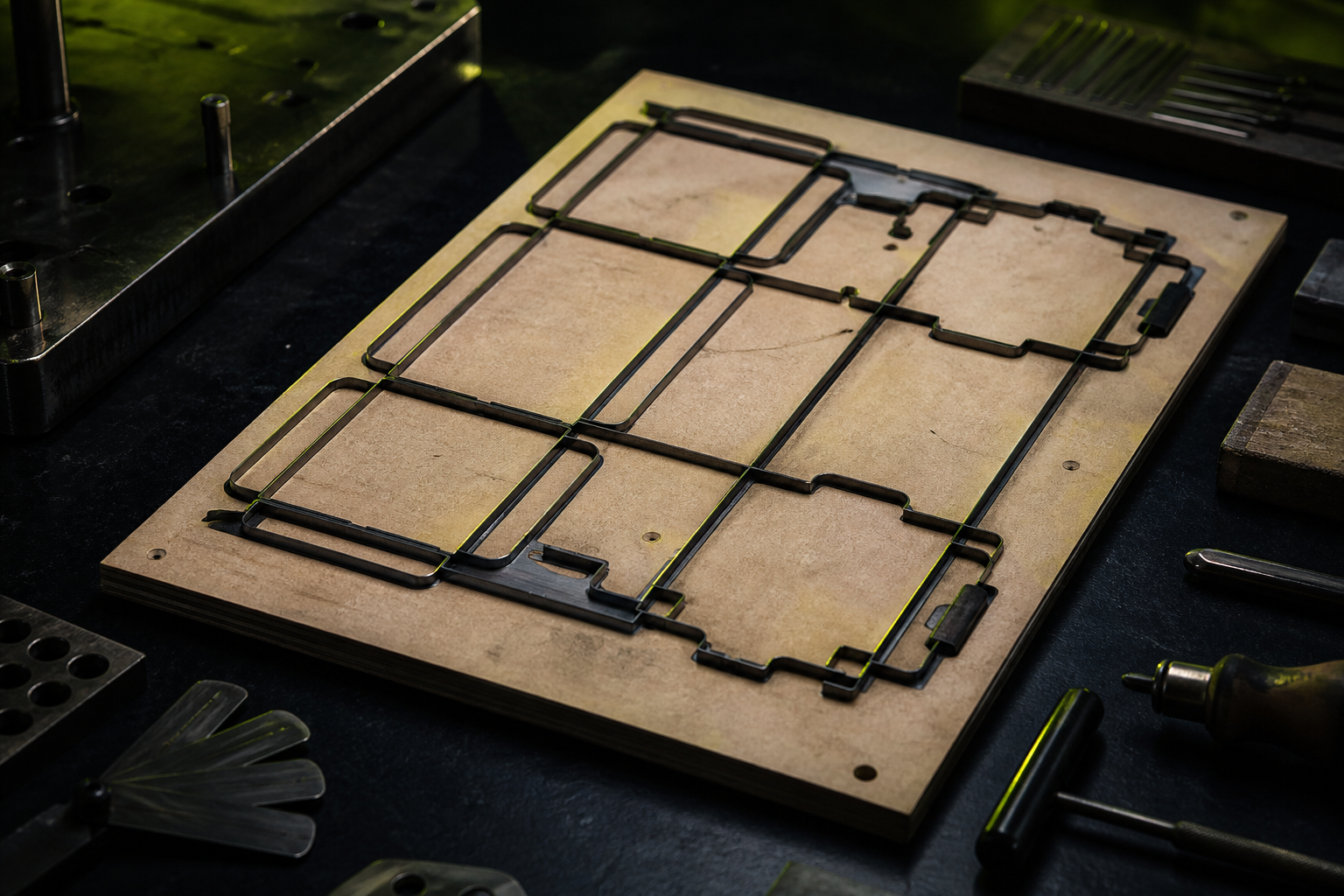
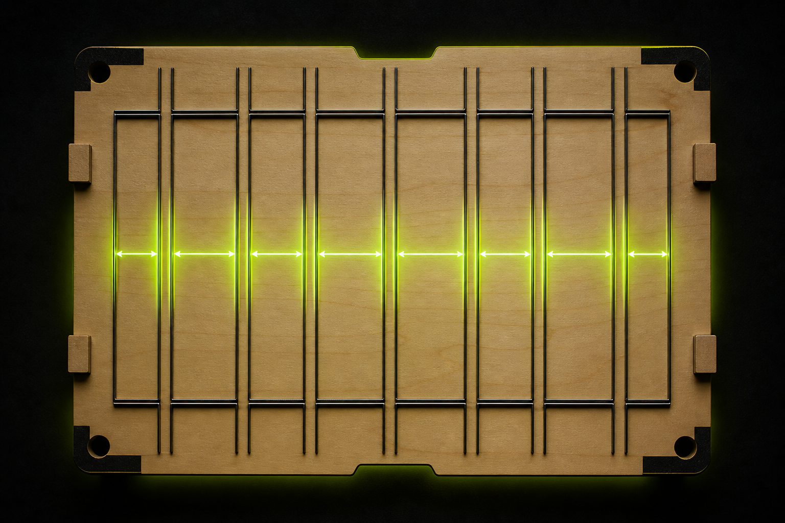
Flatbed laser dies are fast for prototypes and short runs. RULE die (steel rule on wood) suits high volume on platen presses. Die type affects rule thickness, padding and board life.
Laser: prototypes and small series — no steel-rule board cost
RULE die: standard for high-volume print houses
Platen die-cut: needs precise register with lithography
Rotary die: repeating forms on web-fed lines
Laser die vs RULE die.
Checks before handing the file to the die maker
All cut paths closed. Crease as centerline or channel profile per shop spec. No open endpoints on cut paths. Scale 1:1, unit mm. Layers named: CUT, CREASE, PERF.
Preflight: remove duplicate paths
Register marks if print and die-cut run together
Blank orientation matched to board grain if required
PDF + DXF/SVG together
Link to parametric dielines
When the dieline comes from FinalPack’s online tool, Cut and Crease are already parametric and in millimetres — die work shrinks to review, channel tuning and machine export. That path cuts hand-drawing error.
Building a die from a dieline
From blank file to press-ready die board
1
Receive the final dieline
PDF/SVG with separate Cut and Crease layers — preferably from parametric sizing.
2
Technical review
Check rule spacing, crease channel and perforation against press specs.
3
Build the board
Laser cut or RULE die on the board — ejection rubber if needed.
4
Cut test
Sample on real board before handover to production.
FAQ
2pt or 3pt rule for 350 gsm board?
Usually 2pt for folding carton up to about 400 gsm and 3pt for thicker board or kraft. Confirm with your die maker — machine and rule age matter too.
Should crease be dashed or solid?
In design files it is often dashed to distinguish from cut; CNC export may use a solid centerline. Layer separation and naming matter most.
Can I build a die straight from an online dieline?
Vector dieline output is the base; for high volume, a die-designer review and sample cut are still recommended.
What is the minimum distance between cut and crease?
Depending on board thickness and rule type, usually 2–4 mm — stated in the die-shop technical spec.